
MILESTONE ELECTRONICS
CONTACT CLOSURE to RS232 CONVERTOR
The ML 4 CCS is a hardware integration device designed to convert 4 channels of dry contact closure inputs into standardized RS232 interface data, enabling direct tracking and control interface communication with host control computers.
- Converts 4 independent dry contact closure signals into numeric RS232 serial data
- Features built-in toggle switcher logic for executing dual functions from a single contact point
- Equipped with dedicated rear-panel DIP switches for altering the trailing ASCII termination character
- Provides continuous hardware monitoring via real-time LED indicators for Power and RS232 output status
- Includes plug and play architecture requiring no external software setup during physical installation
Max Resolution
1080p Full HD
Audio Input
Stereo Analogue
Output
Single HDMI
- In-house manufactured
- 2,000+ clients served
- In-house manufactured
- 24hr response
- 2,000+ clients served
Product Overview
What the ML 4 CCS delivers
The Contact Closure to RS232 Convertor by Milestone is a dedicated hardware solution that assists system programmers and engineers in converting manual contact closures into machine readable RS232 interface data. The ML 4 CCS model specifically handles 4 physical contact closures, translating mechanical shorting states into instantaneous serial telemetry strings.
The system integrates an adjustable toggle switch function located on the rear panel. When turned on, this logic configuration changes a single contact input into a dual function mechanism, enabling the system to alternate between separate command structures on successive closures of the identical terminal point.
Data transmission parameters are strictly configured for industrial control standards, operating at a fixed 9600 baud rate with an 8-bit word structure, 1 stop bit, and no parity. Output strings comprise custom numeric designators and configurable ASCII terminator codes adjusted through onboard DIP switches, ensuring seamless compatibility with legacy or modern automation software modules.
Total Contacts
4 Pin Screws
Output Port
Baud Config
Dual Function
ASCII Adjust
Power Source
Need a quote?
Our team responds within 24 hours with a tailored quote for your project or bulk order.
Key Features
Reliable integration over contact terminal networks
Hardware based mechanical interface translation featuring advanced logic parameters, structural terminations, and direct status feedback.
4 Channel Contact Processing
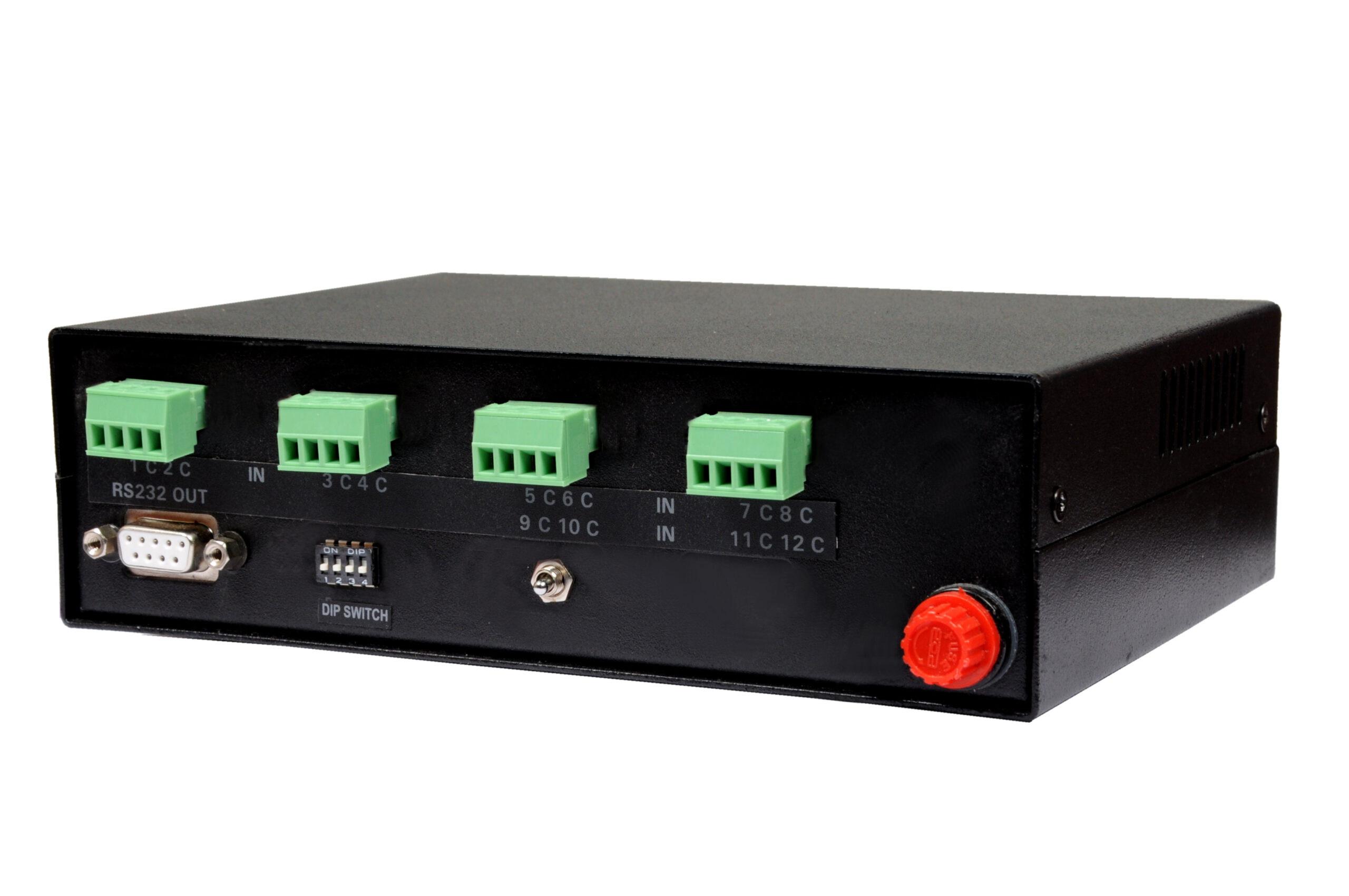
The device handles 4 physical dry contact inputs routed through 4 pin captive screw connectors. Each terminal block accepts wiring for 2 discrete channels alongside a shared common contact point, creating a neat and secure infrastructure for termination.
- Processes 4 contact closures simultaneously
- Secure 4 pin captive screw connection blocks
- Independent channel operation with shared common terminal pin
Dual Function Toggle Switcher
An onboard toggle switcher allows a single physical contact point to perform a dual function logic loop. Operating a channel for the first time outputs an initial primary string, while a consecutive strike triggers an entirely alternate command string.
- Rear panel toggle switch activates dual operating mode
- First click outputs primary character matrix string
- Second click routes secondary command set across same link
DIP Switch Terminations
Built-in 4 position DIP switches let installers map distinct trailing ASCII code symbols to match specific central computer protocols. Toggling the configurations alters the final command terminator symbol immediately.
- Adjusts trailing ASCII code output automatically
- Supports distinct terminator values like exclamation and hash symbols
- Simplifies system integration with third party master engines
Visual LED Feedback Strip
The chassis integrates precise front facing light indicators to simplify local loop testing and regular fault isolation. Dedicated indicators give immediate feedback on system operational health and outbound serial data transfers.
- PWR indicator illuminates upon stable AC mains connection
- RS232 indicator blinks during active data frame transitions
- Speeds up line analysis without external data terminal tests
Plug and Play Architecture
Built completely as an autonomous conversion appliance, the device operates independently of any active microcode loaders or special control software. Wires are fixed directly to terminal pins and operate right out of the box.
- Zero device drivers or loader utilities required
- Immediate transmission upon circuit terminal shorting
- Reduces programming overhead during initial building deployment
Industrial Grade Power Management
Designed to fit right into standard regional industrial grids, the device operates seamlessly with local mains power inputs. The direct integrated transformer infrastructure eliminates the need for separate external wall warts or power modules.
- Direct 230 V AC mains input design
- Eliminates fragile external low voltage power supplies
- Maintains stable execution profiles inside standard racks
Installation
Pin layout and interface wiring configurations
The ML 4 CCS requires minimal wiring adjustments, utilizing structural captive screw terminal interfaces for inputs and standard D-sub connectors for serial infrastructure.
01
4 Pin Captive Screw Termination
Mechanical sensors or dry buttons are connected directly via the 4 pin captive screw connector blocks on the rear interface. Pin 1 and terminal point C form the contact loop for Channel 1. Pin 2 and terminal point C form the contact loop for Channel 2. Subsequent channels follow this sequential configuration across the remaining terminal pairs.
02
RS232 Serial Out Interface
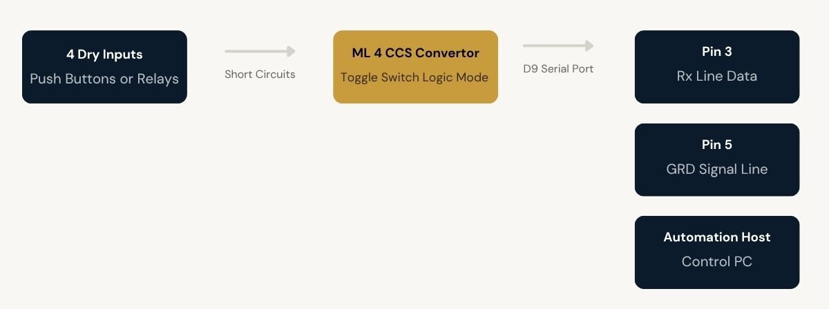
The outbound data link uses a standard D9 female connector block on the rear panel. Hardware signaling follows an industry standard pin map where terminal Pin 3 acts as the receiving lane (Rx) and terminal Pin 5 functions as the common system ground link (GRD). This interface bridges directly to host computer COM inputs.


Where the ML 4 CCS performs
Engineered for industrial tracking environments requiring precise translation of manual switch matrices into standardized serial telemetry lines.
Corporate Boardrooms
Integrates manual wall mounted keypad trigger plates into modern AV master controllers. Pressing standard micro switches generates explicit RS232 characters to trigger customized macro arrays instantly.
Industrial Automation Systems
Bridges simple limit switches, relay outputs, or physical machine guard gates into local computer surveillance networks. Mechanical closure changes map instantly into machine readable hexadecimal messages.
Educational Presentation Systems
Allows instructors to operate central AV processors using physical custom podium buttons. Toggle switcher configuration enables a single physical console switch to alternate functions sequentially.
Security Control Center Terminals
Routes panic push switches or mechanical alarm loop outputs directly to main monitoring computers, delivering precise ASCII alert signals immediately when a switch contact point drops.
AV Rack System Integration
Acts as a direct termination block for third party control units within an equipment rack, converting remote relay closure states into immediate single line serial control operations.
Broadcast Studio Facilities
Bridges mechanical tally lights or simple operator desk status toggles directly into the studio network, feeding real-time positional serial telemetry straight to central master arrays.
Full specification sheet
- Input Specifications
- Serial Interface Parameters
- Logic and Termination Control
- Hardware and Electrical
FAQs about the Contact Closure to RS232 Convertor
What is the Contact Closure to RS232 Convertor (ML 4 CCS) used for?
The Contact Closure to RS232 Convertor by Milestone is a specialized hardware integration unit used to convert mechanical contact closures into standardized RS232 interface data. It helps technical operators feed standard push buttons, relays, or mechanical sensor triggers into an automation computer by instantly converting the dry contact shorting state into continuous serial command characters.
How many contact closures does the ML 4 CCS support?
The ML 4 CCS model supports up to 4 independent contact closures. These inputs are terminated using 2 separate 4 pin captive screw blocks on the rear panel, where each physical connection block handles wiring for 2 discrete channels alongside their respective shared common terminal points.
What serial communication settings does the convertor use?
The device operates under fixed industrial serial protocols. Outbound commands are directed through the D9 female serial connector under a set communication speed profile of 9600 baud rate, 8-bit data word length, 1 stop bit, and no parity checking parameters.
How does the dual-function toggle switch feature operate?
When the dedicated toggle switch at the rear end is set to ON, the converter activates an inner dual function logic engine. Striking Channel 1 for the first time will send a regular 1! character string, while striking the identical channel a second consecutive time updates the code loop to route an alternate A! character string across the serial link.
Can I change the terminal ASCII string character?
Yes, the trailing ASCII code termination character depends completely on the structural position of the 4 position hardware DIP switch array built into the unit. By shifting the position selectors between ON and OFF patterns, engineers can modify the default termination symbol from an exclamation point to a hash mark, commercial at symbol, percent sign, ampersand, or colon character to match master software protocol structures.
Does the ML 4 CCS require an external power brick?
No. The device features integrated power transformation circuitry designed for heavy duty installations. It links directly to a standard 230 V AC mains input connection, removing the need for loose external low voltage DC wall adapters and providing a secure power link within heavy rack groupings.
Products you may also need
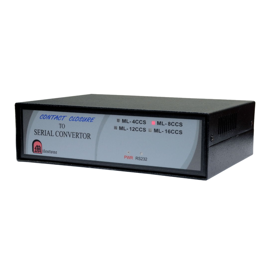
The ML-16CCS converts up to 16 contact closure inputs into RS232 serial output data....
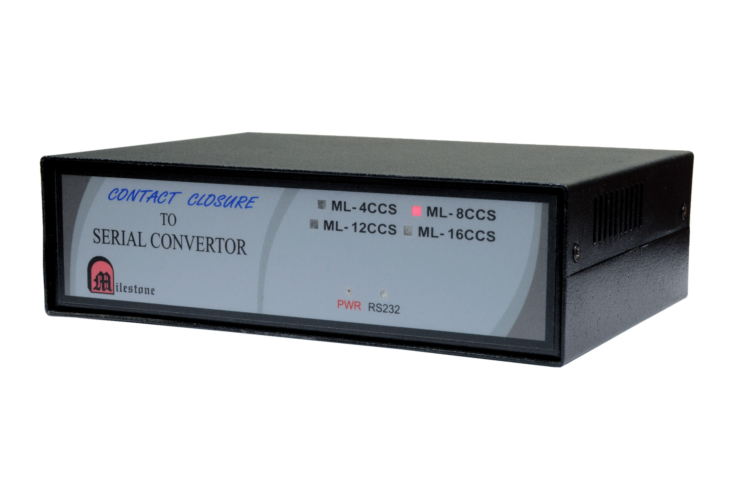
The ML-8CCS converts 8 independent contact closure inputs into RS232 serial output data. Each...
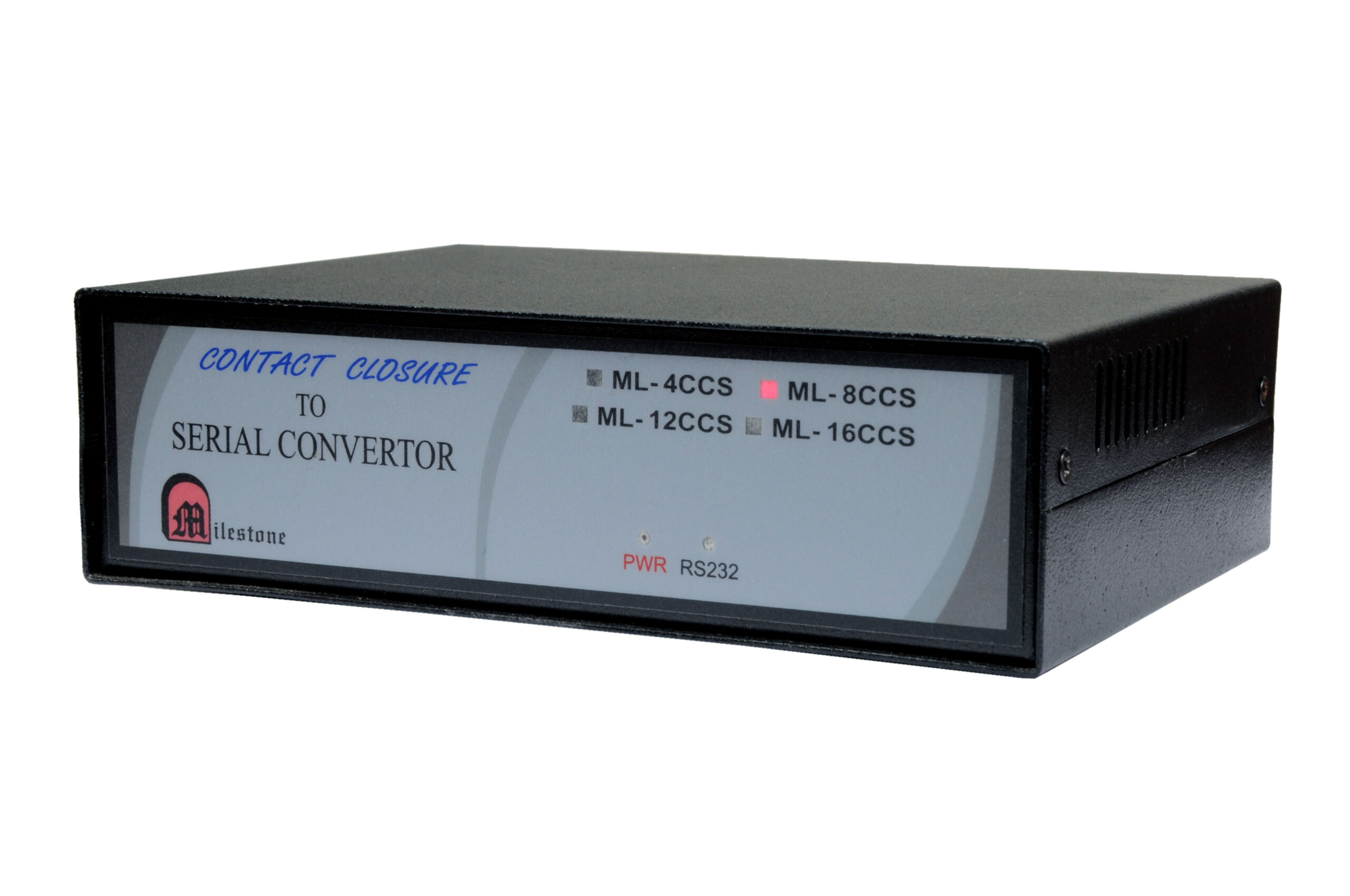
The ML 4 CCS is a hardware integration device designed to convert 4 channels...
Ready to order or have a specific requirement?
Our team responds within 24 hours. Bulk pricing, custom solutions, and pan-India delivery are available. Talk to an engineer directly about your setup.