
MILESTONE ELECTRONICS
8 I/O CONTROLLER
The 8 I/O Controller by Milestone helps control various electric appliances specifically for Look at me applications like microphones and cameras from multiple places using input contact closure or local keypad selection.
- Features 8 optically isolated relay outputs rated up to 24V, 500ma
- Individual relay toggle control through local front panel keypads 1 to 8
- Equipped with a 3 Bit DIP switch unit identifier code supporting up to 64 units
- Includes RS232 interface for external serial control commands and responses
- Battery backed memory features retain last selected relay status at power ON
Optical
Max Resolution
1080p Full HD
Audio Input
Stereo Analogue
Output
Single HDMI
- In-house manufactured
- 2,000+ clients served
- In-house manufactured
- 24hr response
- 2,000+ clients served
Product Overview
What the ML-8 I/O delivers
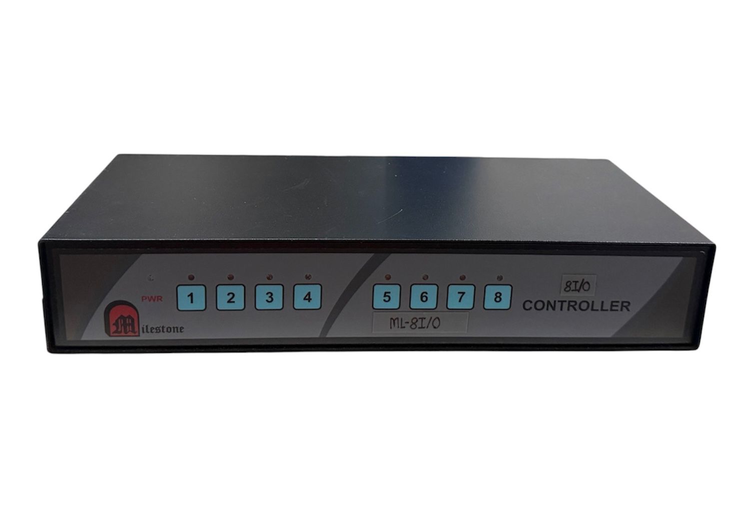
The ML-8 I/O Controller is a professional-grade hardware platform designed to coordinate electrical appliances from multiple operating positions. It is optimized for Look at me switching applications involving professional microphones and camera feeds, allowing streamlined operations sitting at multiple places through input contact closure signals.
This controller incorporates eight output relays that are completely optically isolated to protect sensitive upstream control logic from high surge currents or volatile line drops. The terminal interfaces utilize dependable captive screw connect mechanisms, which prevent loose wiring faults across rigorous long term production schedules.
The unit features integrated front panel keypads numbered 1 through 8, allowing manual control and local monitoring alongside automated triggers. Pressing an individual keypad toggles the corresponding relay state directly, which is indicated instantly via the corresponding LED panel lights.
To enable scalable network engineering, the module incorporates a 3 Bit DIP switch for assigning explicit unit identity codes. When integrating multiple control systems, users can scale operations up to 64 output contact closures or send direct automated command strings over standard RS232 communication lines via a dedicated 3 pin interface.
Relay Count
Switching Capacity
Isolation Type
ID Configuration
Memory Retention
Power Source
Need a quote?
Our team responds within 24 hours with a tailored quote for your project or bulk order.
Key Features
Reliable Relay Control and Serial Signaling
Industrial-grade input/output management featuring plug and play installation, robust optical isolation, and battery backed system memory.
Easy Plug and Play Installation
The controller is engineered for rapid deployment across diverse project environments. It features an intuitive, plug and play installation design that removes complex startup sequencing or extensive software dependencies, ensuring immediate system availability upon connection.
- Minimal integration setup time required
- Streamlined terminal deployment architecture
- Reduces field calibration errors during installation
Optically Isolated Relay Outputs
To protect host network infrastructure from severe damage caused by high voltage transients or feedback surges, all 8 output relays feature complete optical isolation. This structural separation maintains clean operational boundaries between signal logic and driven loads.
- Protects sensitive central command equipment
- Ensures safe 24V, 500ma load switching bounds
- Enhances system resilience against line spikes
Dual Keypad and Contact Input Control
The system delivers versatile control flexibility by supporting execution via physical input contact closures as well as a local front panel keypad. Pressing individual keypads or shorting corresponding contacts toggles the target relay state instantly between ON and OFF.
- Local 1 to 8 keypad selectors for manual override
- Contact closure shortcuts allow automated execution
- State switching logic operates cleanly on toggle parameters
3 Bit DIP Switch Unit Identity Mapping
An onboard 4 bit, 3 bits active DIP switch configuration provides hardware address definition from code A through H. This identifier block enables complex multi unit clusters to co exist on shared lines without signal overlap or cross command conflicts.
- Eight explicit identity code states from A to H
- Enables multi unit control topologies across shared layouts
- Simplifies field address configuration adjustments
Scalable Multiple Unit Operations
By combining distinct unit identifier codes, system integration layouts can scale to support up to 64 output contact closures. The control architecture transmits direct RS232 command packets initiated using 64 separate input contact closures across the local cluster.
- Coordinates comprehensive multi device control fields
- Transmits structured serial commands through input closures
- Provides expansive signal distribution capability
Battery Backed State Memory Retention
The internal circuitry integrates dedicated battery backed memory systems to secure operational persistence during critical power drops. At power ON, all output relay states return directly to their last selected status prior to the power termination event.
- Prevents broad device initialization failures after resets
- Maintains constant state status verification
- Eliminates the requirement for software recovery commands
Installation
Hardware Terminals and Interconnect Wiring
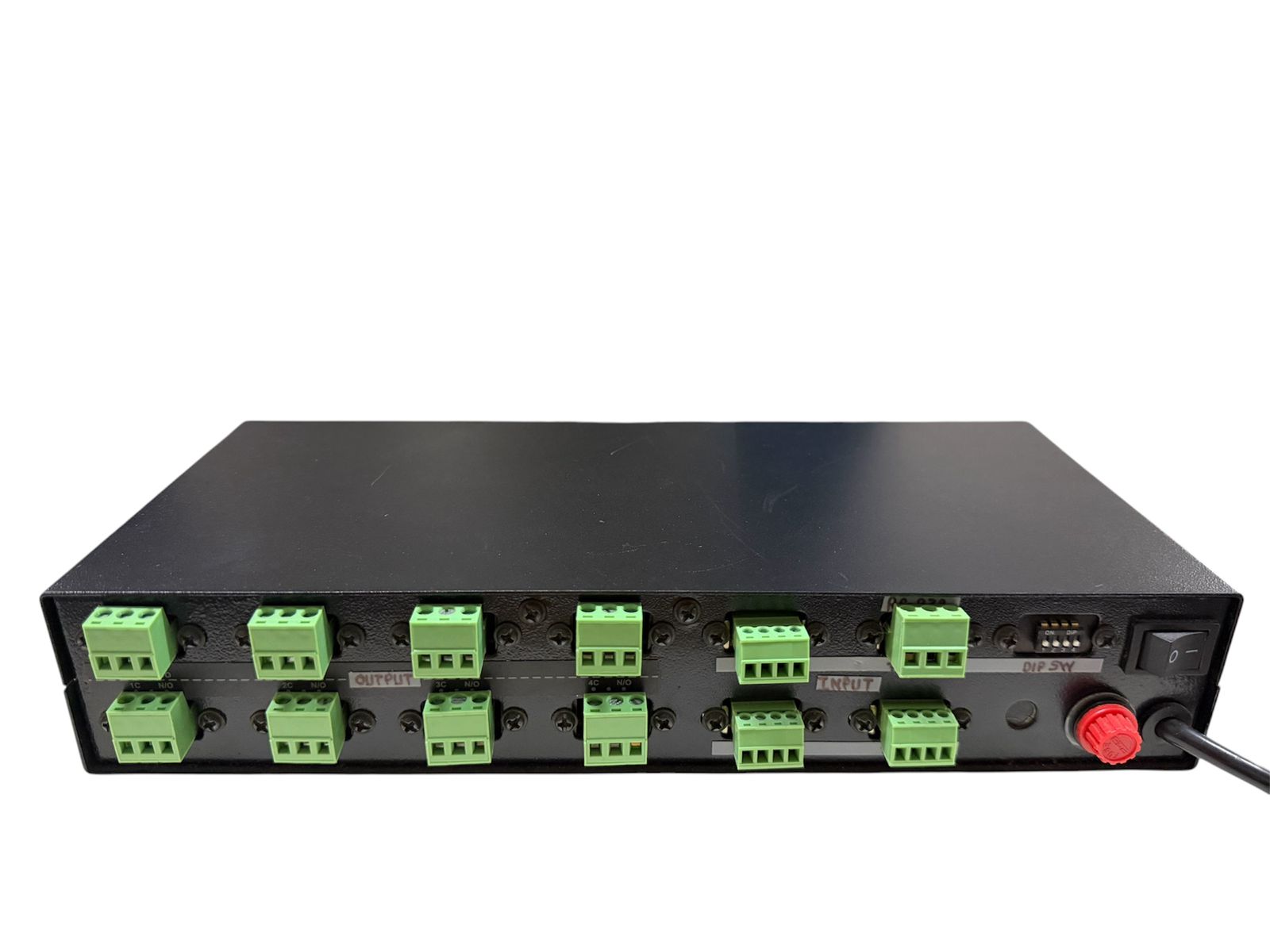
The ML-8 I/O provides modular captive screw connections for input contact strings, external RS232 links, and independent relay channels.
01
Input Contact Closure Wiring
The unit incorporates three distinct 4 pin captive screw input connectors to manage external contact lines. Inputs 1 to 3, 4 to 6, and 7 to 8 are wired alongside a shared ground (GRD) point. Shorting any target input pin to the ground line instantly triggers a toggle command sequence for that output relay channel.
02
Output Relay Terminal Connection
Eight individual 3 pin output captive screw assemblies provide physical interfaces for driven appliances. Terminal pin maps correspond to Common (C) and Normally Open (N/O) configurations. The center points of all captive screw assemblies are shorted internally to maintain structural connection baselines.


Where the ML-8 I/O excels
Engineered for high reliability industrial and professional audio video infrastructure environments where remote device trigger sequencing is mandatory.
Look at me AV Switching Networks
Coordinates automated input selection systems for high priority cameras and target microphone arrays during collaborative live production events or automated broadcast capture sessions.
Multi Point Corporate Meeting Environments
Allows board participants situated across separate table locations to command local AV equipment states safely through localized physical switch inputs or desktop keypad modules.
Automated Lecture Hall microphone routing
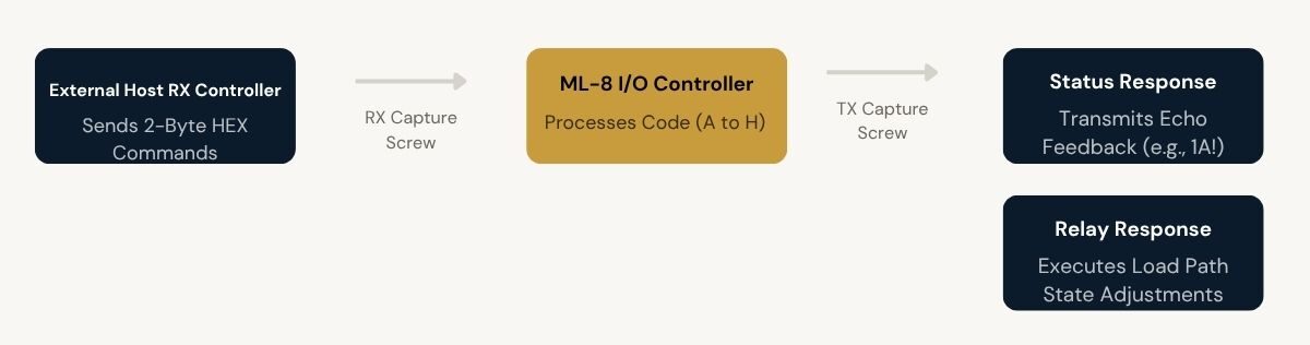
Manages multi microphone environments across wide learning spaces, routing audio paths cleanly via contact closure triggers while broadcasting confirmation flags over RS232 back to host consoles.
Secure Industrial Control Centers
Delivers robust optical isolation bounds to manage secondary machinery components safely without generating line noise feedback into precision tracking computers or monitoring displays.
Camera Array Position Triggering
Integrates directly with remote recording equipment arrays, initiating target frame sequences based on real time input shorts without encountering timing latency variations.
Distributed Hardware Control Racks
Leverages the 3 Bit unit identity coding matrix to drive multi module equipment operations containing up to 64 output relays from centralized deployment hubs.
Full specification sheet
- Relay Output Parameters
- Input and Management Interfaces
- Serial Communication Parameters
- Physical and Power Configurations
FAQs about the 8 I/O Controller
What is the 8 I/O CONTROLLER (ML-8 I/O) used for?
The 8 I/O Controller is designed to allow individuals to control various electric appliances sitting at multiple places through input contact closure signals. It is optimized specifically for Look at me switching applications, such as coordinating system microphone feeds and camera capture hardware components from separate monitoring endpoints.
How far can this controller transmit signals?
While baseline dry contact distance parameters depend on physical link resistance thresholds, systemic extension limits can scale out by integrating multiple modules. Utilizing the onboard Unit Identifier hardware system allows systems to bridge control signals over multi unit architectures to manage up to 64 output contact closures and execute serial command packets across wider network areas.
Will the signal transmission remain clear over long distances?
Yes, signal clarity and operational safety are structurally maintained. The controller isolates all output relays using high performance optical separation modules. This configuration blocks volatile voltage feedback waveforms or high surge currents from passing into the internal processing components, preserving system stability across expansive setups.
Can I control my device from another room?
Yes, remote operational control is supported. By connecting remote buttons or switcher panels to the 4 pin input captive screw connectors, you can run dry contact trigger wires from separate spaces. Shorting an input pin to the ground line inside that room immediately changes the operational state of the corresponding isolated relay output on the core unit.
Where is the controller commonly used?
The ML-8 I/O Controller is widely integrated across professional corporate boardrooms, multi seat meeting facilities, educational broadcast presentation centers, and video production stages. It is ideal for any technical setup where multiple operators must securely trigger shared electronic equipment like microphones or camera hardware lines.
Can one controller manage multiple appliances at the same time?
Yes, the hardware includes eight completely separate output relays rated up to 24V, 500ma to drive multiple independent electrical loads. Individual channels can toggle their operating states simultaneously through local front panel keypad selection buttons 1 to 8, remote input closures, or incoming RS232 serial commands.
Does this controller require any specialist cabling?
No specialized proprietary cabling is required. All inputs, outputs, and RS232 connections utilize standard commercial wire strands fastened directly into physical 3 pin and 4 pin captive screw terminal blocks. This ensures dependable wiring integration without needing specialized termination tools or prefabricated cable molds.
What happens to the relay states if the controller encounters a power loss?
The module is designed with built in operational persistence. It features an integrated battery backed memory module that continuously saves relay status records. When mains power is restored, all output relays automatically return to their exact previous operational state as selected before the power disruption occurred.
What are the precise serial port parameters for sending RS232 commands?
The RS232 serial link communicates using a fixed protocol profile of 9600 baud, 8 data bits, 1 stop bit, and no parity checking rules. Automated control commands accept precise 2 byte hex inputs that match designated address target ranges, such as sending 31 41 to activate relay 1 on a unit mapped to address code A.
Products you may also need
Ready to order or have a specific requirement?
Our team responds within 24 hours. Bulk pricing, custom solutions, and pan-India delivery are available. Talk to an engineer directly about your setup.