
MILESTONE ELECTRONICS
CONTACT CLOSURE to RS232 CONVERTOR
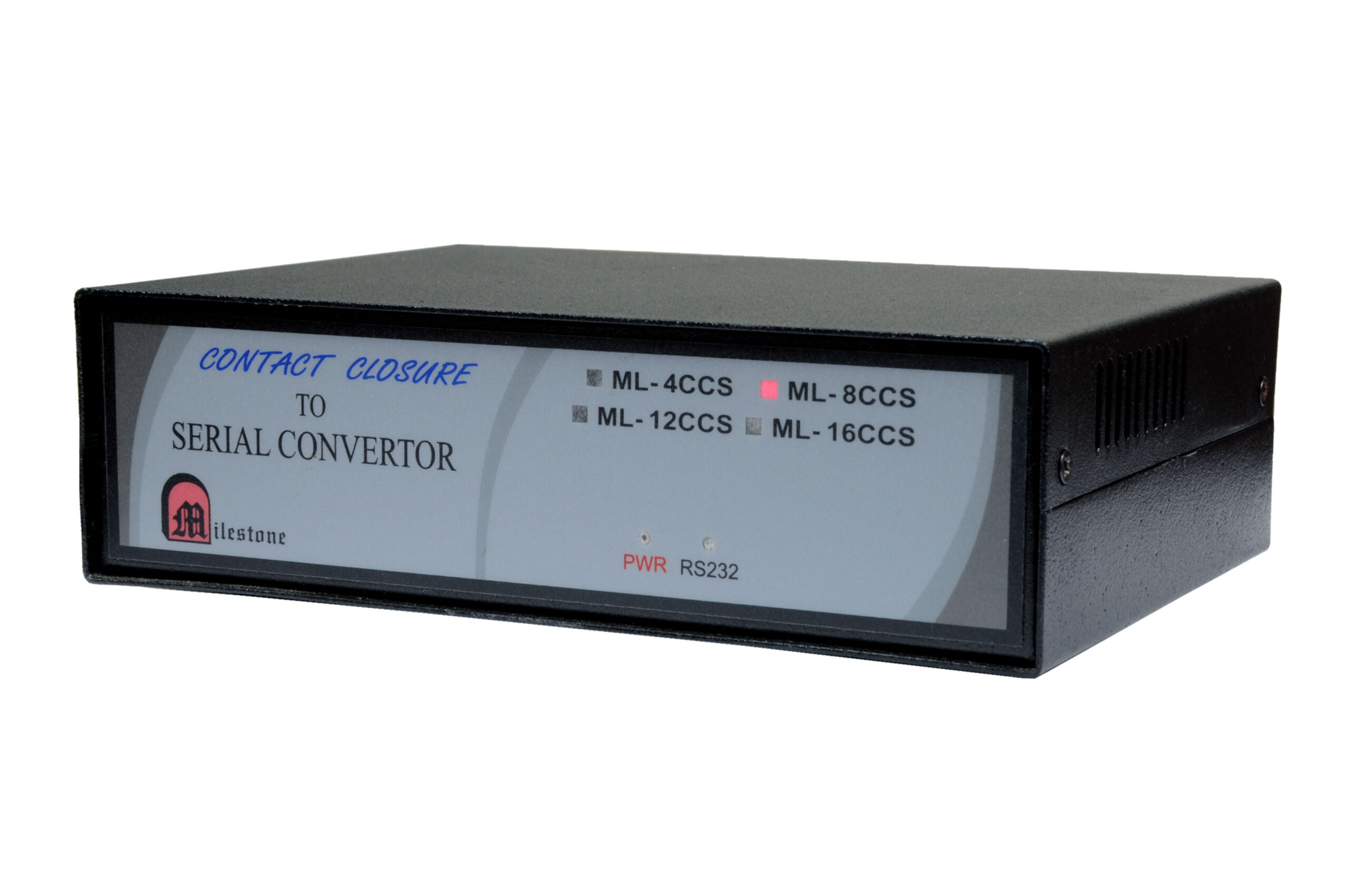
The Contact Closure to RS232 Convertor by Milestone is an industrial grade hardware device that helps persons to convert contact closure hardware input signals into clear serial RS 232 interface data streams, managed through dedicated 4 pin captive screw connection blocks.
- Converts up to 12 distinct contact closure inputs into serial RS232 interface data
- Features 6 standard 4 pin captive screw connection ports supporting 2 channels each
- Integrated dual function capability via dedicated toggle switcher control mechanics
- Dedicated front panel LED indications for both power status and active RS232 serial output
- Simple plug and play installation routine requiring minimal system configuration steps
Max Resolution
1080p Full HD
Audio Input
Stereo Analogue
Output
Single HDMI
- In-house manufactured
- 2,000+ clients served
- In-house manufactured
- 24hr response
- 2,000+ clients served
Product Overview
What the ML 12 CCS delivers
The Contact Closure to RS232 Convertor model ML 12 CCS is a purpose engineered hardware interface device designed to bridge physical dry contact terminal states with standard serial network control architectures. The system translates physical closing loops into precise digital hexadecimal and decimal code messages output directly through a rear panel interface.
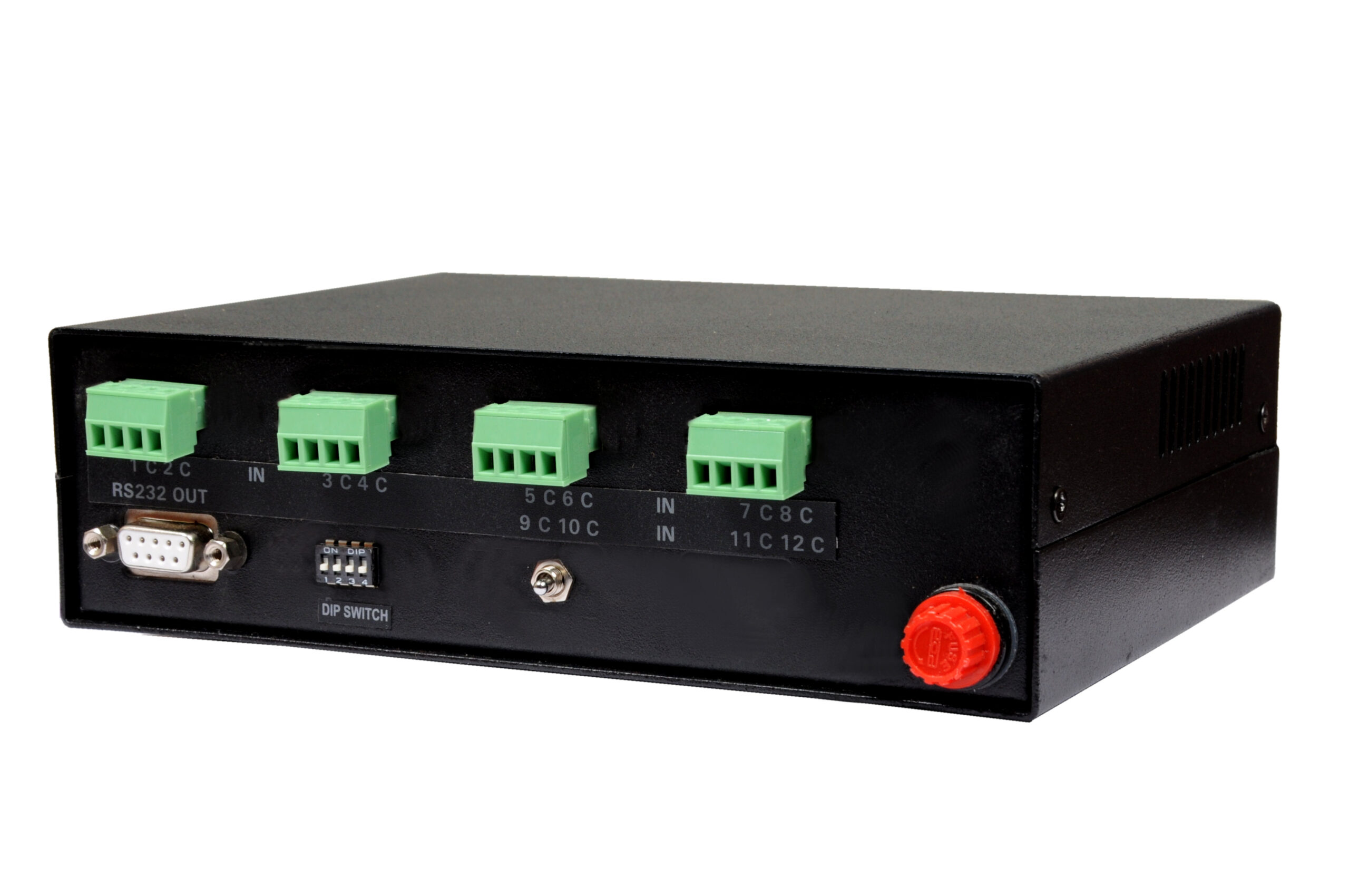
The system utilizes 4 pin captive screw connection modules where each terminal block handles 2 standalone input channels. Terminal mapping points match standard numbering schemes where point 1 and common point C serve channel 1, and point 2 and common point C serve channel 2, repeating uniformly across all 12 supported contact channels.
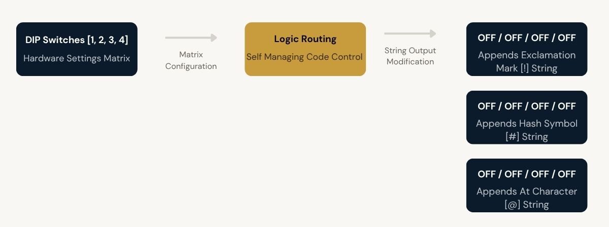
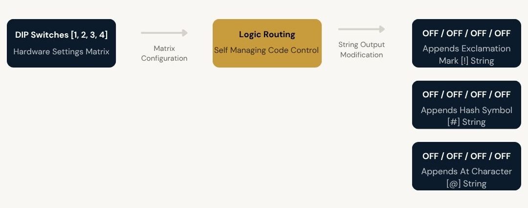
Advanced system adjustment mechanisms are handled directly via a layout of structural DIP switches on the enclosure. By altering the position combination of DIP switch numbers 1, 2, 3, and 4, operators can adjust the trailing ASCII code validation character emitted with each message string, switching between standard communication marks like exclamation marks, hashes, and question marks.
To enable multi layered operation parameters, the ML 12 CCS integrates a dedicated physical toggle switch component at the rear terminal section. When active, this switch grants single contact points dual control functions, alternating the emitted data between distinct primary decimal and secondary double contact hex string blocks upon consecutive physical activations.
Contacts Supported
Screw Blocks
Serial Out Port
Baud Parameter
Data Settings
ASCII Adjustment
Operational Mode
Need a quote?
Our team responds within 24 hours with a tailored quote for your project or bulk order.
Key Features
Reliable digital signal translation hardware
Industrial grade conversion of physical wire loops into serial data strings, featuring dual function triggers, clear monitoring indicators, and custom terminal routing blocks.
12 Channel Contact Loop Processing
The hardware processes up to 12 distinct dry contact closure inputs simultaneously. It systematically translates physical short loops across terminals directly into clear, digital serial control codes without processing overlap.
- Manages 12 independent mechanical contact state entries
- Direct translation into consistent serial command outputs
- Maintains distinct signal tracking for each assigned interface loop
Captive Screw Terminal Infrastructure
Engineered with 6 rugged 4 pin captive screw connection blocks to terminate incoming control wiring securely. Each dedicated terminal grouping accepts bare wires and cleanly services 2 input signal channels.
- Employs exactly 6 industrial grade terminal connector blocks
- Each block handles 2 functional input data lines seamlessly
- Structured common terminal grounding framework for stable reference
Toggle Switcher Dual Function Control
Integrates a dedicated physical toggle switcher module located at the rear housing panel. Enabling this switch activates dual functionality properties, allowing a single contact point trigger to shift output behaviors.
- First physical connection trigger emits primary single contact code data
- Immediate secondary connection trigger maps directly to double contact commands
- Expands operational versatility using existing input terminal wiring
Independent Front Panel LED Indicators
Constructed with distinct visual status monitoring indicators on the hardware fascia. Operators can instantly verify system operating parameters and active processing metrics from a distance.
- Dedicated PWR LED confirms safe mains transformer power delivery
- Active RS232 LED blinks visibly during real time outbound data transmission
- Allows prompt visual diagnosis of connection paths directly on site
Adjustable DIP Switch Character Mapping
Features a 4 position physical DIP switch segment on the casing that directly alters system ASCII terminal coding options. Manipulating switches changes the automated command string validation mark.
- Provides 4 active configuration switches for custom output validation
- Maps command strings to standard symbol indicators like exclamation or hash marks
- Alters matching hexadecimal validation variables instantly at the hardware level
Streamlined Plug and Play Installation
The system operates as an architectural integration module requiring no internal software initialization procedures. Installers simply complete wire terminations and power the unit to bring the interface online.
- Straightforward integration process without tricky protocol setup rules
- Standard D9 interface ports ensure clean connection matching
- Internal self managing circuits automate conversion actions continuously
Installation
Contact terminal setup and serial deployment
The ML 12 CCS supports clean structural installation, establishing secure physical contact monitoring paths and standardized outbound serial parameters over integrated connection interfaces.
01
Terminal Block Wire Routing
Incoming mechanical sensors or switches are connected directly to the 6 integrated 4 pin captive screw modules. Each connector pair shares a joint common grounding terminal, marked clearly as C. Pin point 1 and point C complete the transmission loop for the first channel within the block, while pin point 2 and point C satisfy the secondary channel wire route. All 12 channels wire sequentially using this terminal strategy.
02
Serial Interface Parameter Configuration
The outbound data route runs through a single D9 female connector fixed on the rear interface panel. To achieve safe data parsing with connected host computers, terminal control systems, or automation controllers, the listening serial port must match specific hardware properties. Communication parameters are fixed explicitly at 9600 baud rate speed, using 8-bit data width, 1 stop bit architecture, and no parity checking loops.


Where the ML 12 CCS performs
Designed for automated integration networks requiring robust bridging between hardware relay switches and centralized computational tracking machinery.
Industrial Relay Status Monitoring
Links factory mechanical breaker points or power relay terminals directly to localized data terminal machines, feeding switch position logs instantly through structured decimal code messages.
Central Control Room Automation
Channels input pulses generated from facility wall panels back to central processing engines, parsing physical actions into serial data for operating system management software.
Facility Security System Interfacing
Integrates physical security perimeter trip sensors or alarm activation switches, changing physical contact changes into serial string outputs to trigger network capture alerts.
AV Presentation Control Systems
Bridges simple custom projection room desk switches with computing control software, delivering hex command sequences upon physical switch touch commands.
Legacy Infrastructure Diagnostics
Allows old style push buttons or pressure sensor pads to speak with modern software tracking applications by establishing a transparent hardware conversion gateway.
Remote Machine Status Aggregation
Gathers distinct hardware operational state pulses from independent system points and outputs them sequentially through a single standard serial line.
Full specification sheet
- Hardware Classification
- Input Channel Parameters
- Serial Interface Parameters
- User Adjustments and Monitoring
- Electrical Specifications
FAQs about the Contact Closure to RS232 Convertor ML 12CCS
What is the Contact Closure to RS232 Convertor ML 12 CCS used for?
The Contact Closure to RS232 Convertor model ML 12 CCS by Milestone is an industrial purpose hardware tool developed specifically to help users convert incoming dry contact closure loops into digital RS 232 interface serial data strings for automated system management.
How far can this HDMI extender transmit signals?
This hardware does not employ data extension cabling parameters. It accepts physical wire connections from up to 12 distinct dry contact zones directly onto its localized 4 pin captive screw block connectors and pipes data over a standard serial path via its rear D9 connector port.
Will the video quality remain clear over long distances?
The ML 12 CCS convertor is a dedicated digital serial character tracking device, not a video transmission unit. It focuses purely on processing contact terminal loop activations into clean decimal and hexadecimal control strings without managing video signals.
Can I control my source device from another room?
Control transmission is managed by routing physical lines into the captive screw terminals. When an external contact point closes, the convertor automatically creates and pushes serial text bytes directly to a paired master tracking terminal or local host computer.
Where is the HDMI IR Extender commonly used?
This multi channel contact closure terminal unit is widely integrated within automated operations control rooms, legacy status monitoring setups, electrical relay signal diagnostic frameworks, and general industrial plant connectivity systems requiring physical wire state tracking.
Can one transmitter send the signal to multiple displays at the same time?
The unit uses a point to point serial tracking methodology. Outbound command strings are transmitted exclusively through a single rear panel D9 female port connector that feeds data down a dedicated point to point wire path directly into one receiving serial terminal socket.
Does this extender require any specialist cabling?
No specialized networking cables are required. Contact wiring attaches simply using bare wiring loops straight inside the captive screw terminal slots, while the system output line connects using standard D9 connector cabling configured to link with pin 3 and pin 5 serial paths.
How does the rear panel toggle switcher affect the contact channel behavior?
When the physical rear toggle switch is set to ON, single input contact channels switch to dual function execution mode. Operating the contact line for the first initial instance pushes single contact string codes like 1!, while activating it a second consecutive time emits separate double contact data like A!.
What are the necessary communication interface settings for the listening serial device?
The host processing terminal must match the static internal configuration of the convertor exactly. Operational connection parameters require a fixed 9600 baud rate speed configuration, an 8-bit data character width structure, exactly 1 stop bit length termination, and no active parity checking loops.
Products you may also need
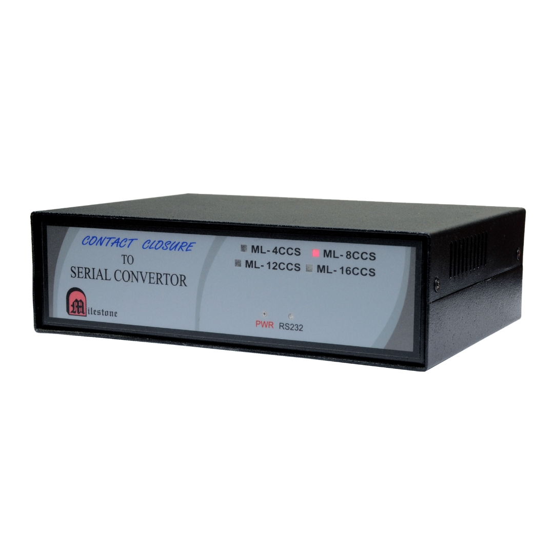
The ML-16CCS converts up to 16 contact closure inputs into RS232 serial output data....
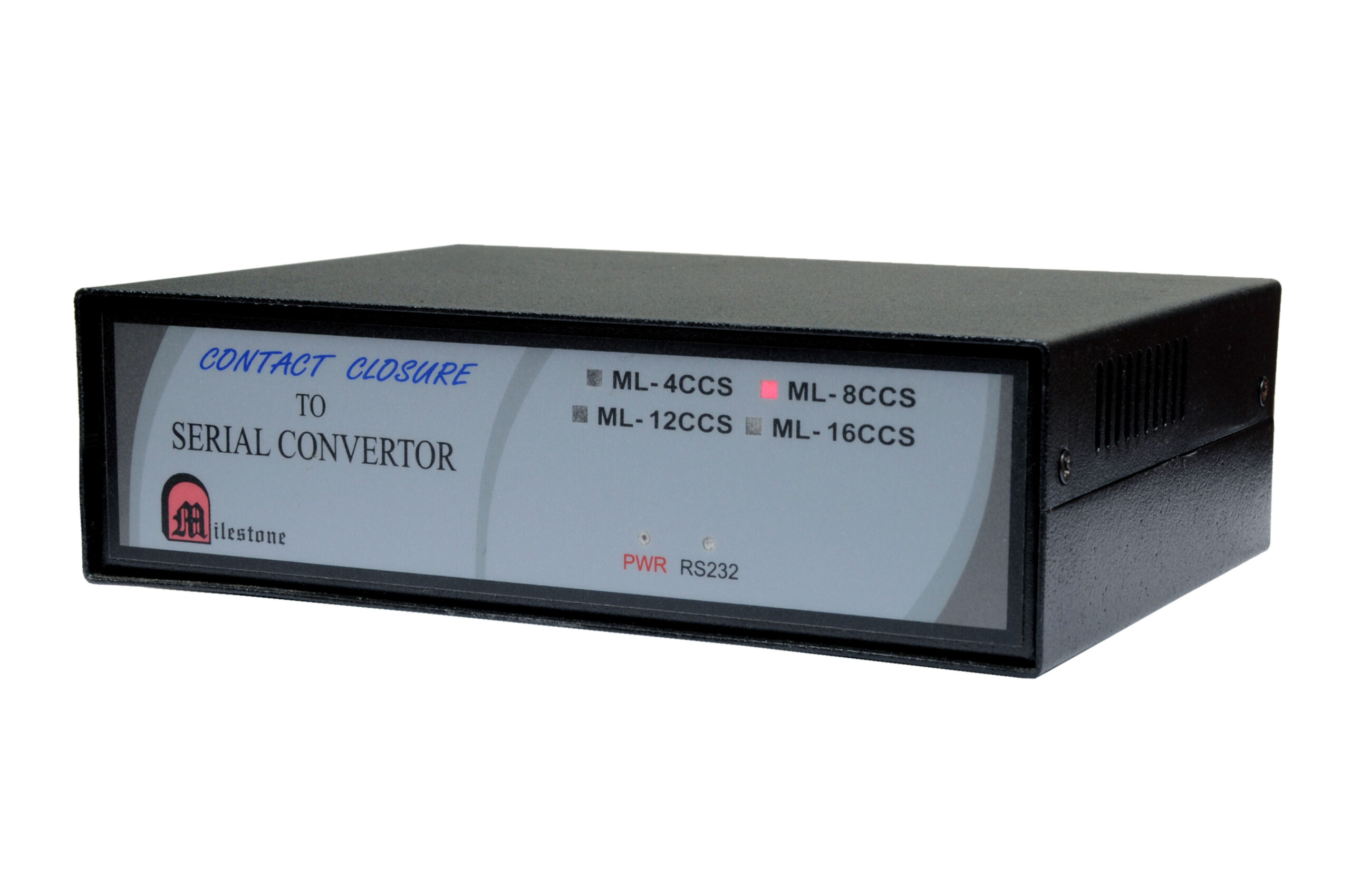
The ML-8CCS converts 8 independent contact closure inputs into RS232 serial output data. Each...
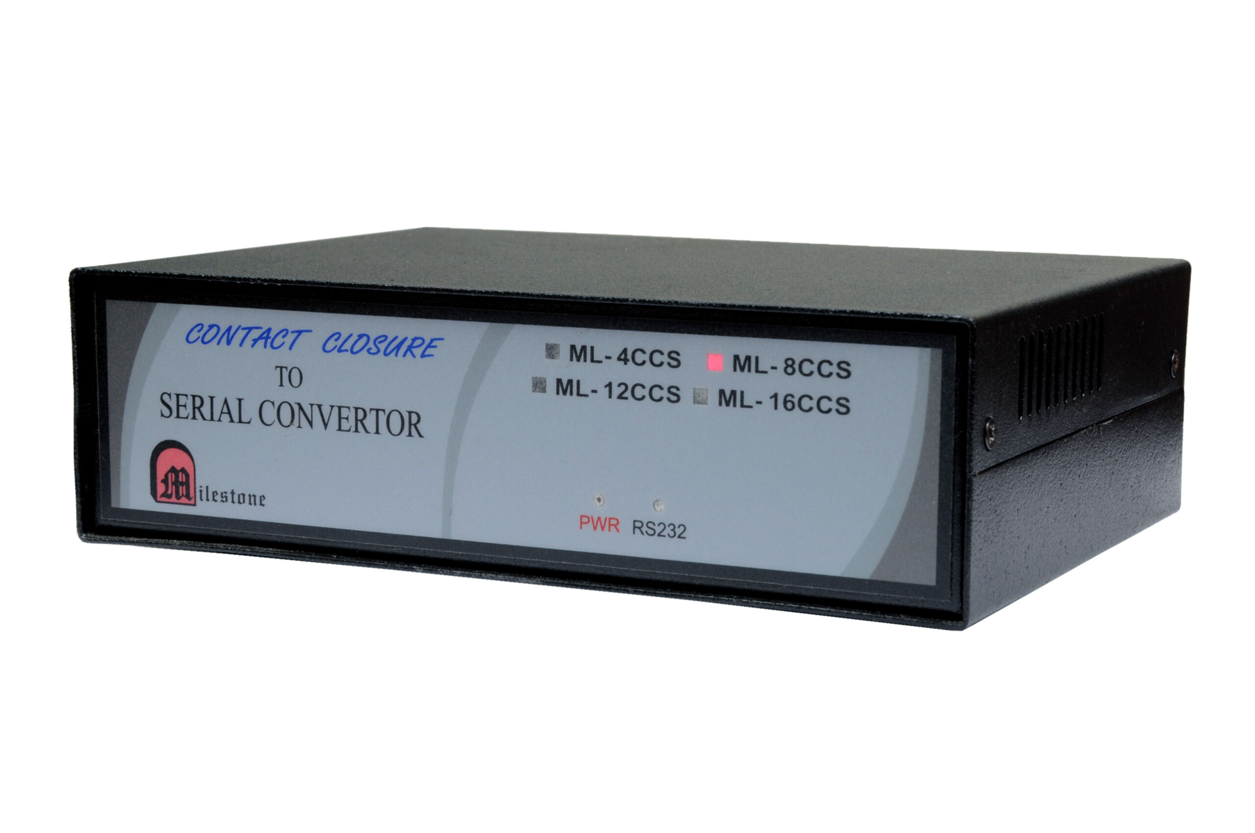
The ML 4 CCS is a hardware integration device designed to convert 4 channels...
Ready to order or have a specific requirement?
Our team responds within 24 hours. Bulk pricing, custom solutions, and pan-India delivery are available. Talk to an engineer directly about your setup.