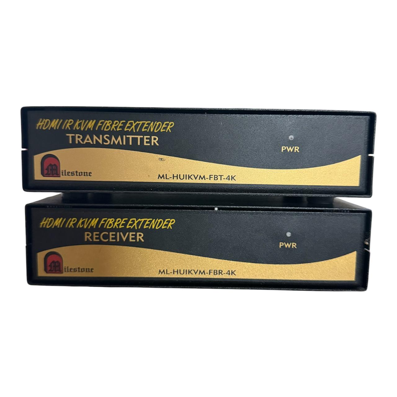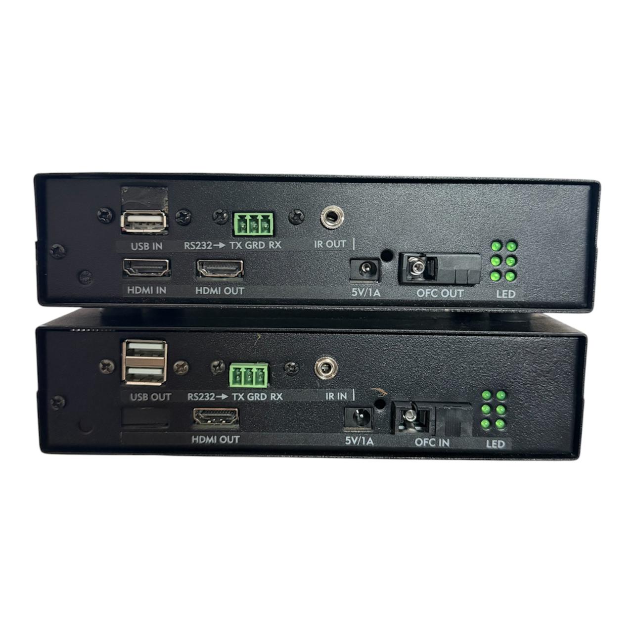
HDMI IR KVM FIBRE EXTENDER-(4K)
Milestone’s ML-HUIKVMFBT-4K/ML-HUIKVMFBR-4K HDMI IR KVM FIBRE EXTENDER-(4K) transmits HDMI, USB KVM, IR and RS232 signals up to 20 kilometres over a single mode, single fibre cable. It supports 4K @ 30Hz video with HDCP compliance for point-to-point installations, or point-to-multipoint installations using a Fibre Switch.
- 1 composite AV input distributed to 4 independent AV outputs
- Audio and video signals transmitted together without delay or mismatch
- Each output individually managed and amplified for consistent signal strength
- Video bandwidth up to 90 MHz (-3dB) with 75-ohm impedance matching
- Rugged metal enclosure with captive screw audio connectors for fixed installations
Max Resolution
1080p Full HD
Audio Input
Stereo Analogue
Output
Single HDMI
- In-house manufactured
- 24hr response
- 2,000+ clients served
Product Overview
What the ML-HUIKVMFBT-4K/ML-HUIKVMFBR-4K delivers
The HDMI IR KVM FIBRE EXTENDER-(4K) from Milestone Electronics consists of two units, the ML HUIKVM-FBT-4K Transmitter and the ML HUIKVM-FBR-4K Receiver. Together they transmit and distribute HDMI, USB KVM, IR and RS232 signals to a distance of 20 kilometres through a single mode, single fibre cable. A Point to Point installation uses one Transmitter and one Receiver, while a Point to Multipoint installation uses one Transmitter and N Receivers connected through a Fibre Switch.
The system supports video resolutions up to 4K at 30Hz and is HDCP compliant, working with all HDMI ports up to 4K. Installation is plug and play, requiring no software configuration on either unit.
Beyond video, the Transmitter accepts a USB input, while the Receiver provides two USB OUT ports for connecting a keyboard and mouse at the display end, giving full KVM control of the source from a remote location. IR extension is also supported, an IR LED is fixed at the source and connected to the IR OUT port of the Transmitter, while an optional IR Sensor cable connects at the IR IN port of the Receiver. Both units also carry RS232 input and output through a 3 Pin Phoenix connector, allowing serial control signals to be passed alongside the video, KVM and IR data.
Each unit displays status through six LED indicators on the rear panel, covering power, Fdx/co, Rx (Link/Act), Tx (Link/Act), Fx100 and Tx100, giving installers an instant view of power and fibre link health. The system also follows the standard IEEE-568B CAT5 cable standard for its control wiring.
ML-HUIKVMFBT-4K/ML-HUIKVMFBR-4K
Need a quote?
Our team responds within 24 hours with a tailored quote for your project or bulk order.
Key Features
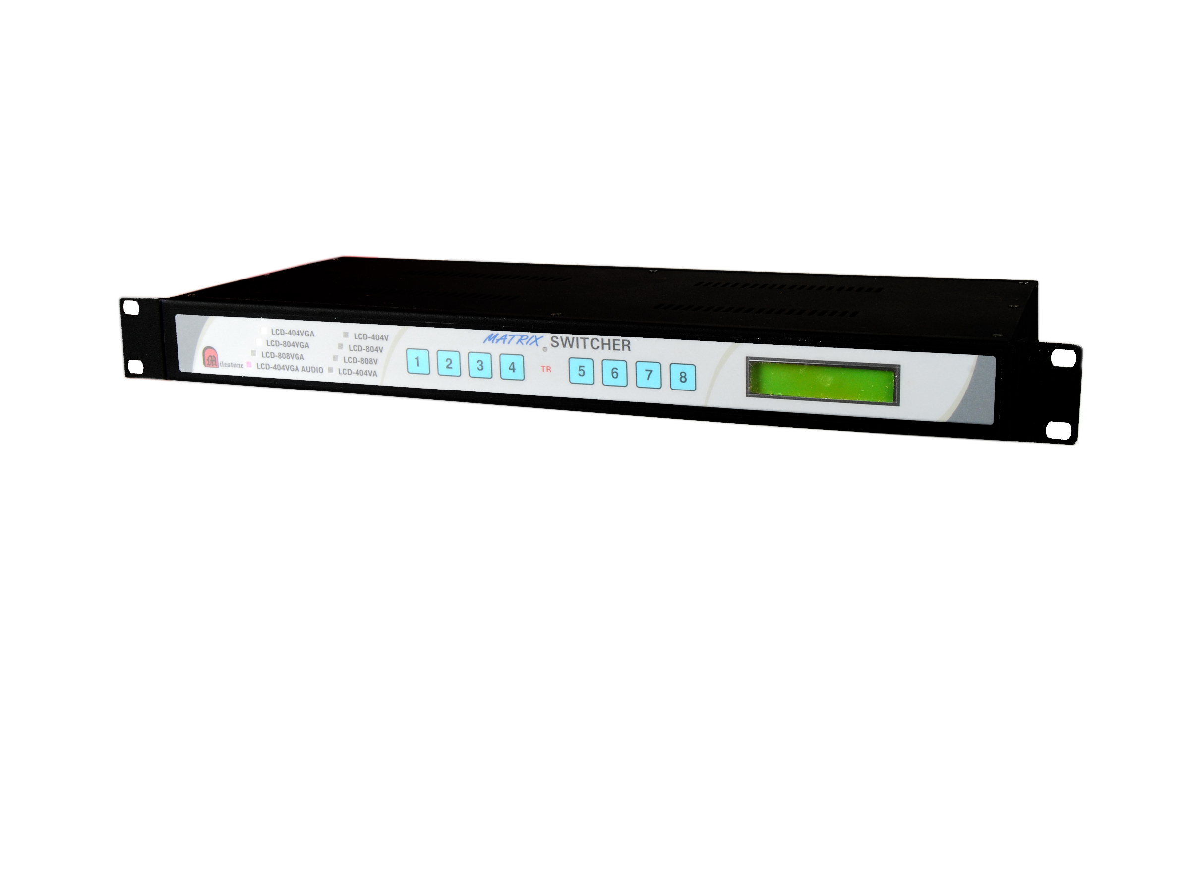
4-input, 4-output VGA matrix switching with multiple control options
Separate Amplified VGA Outputs
Each of the four output ports delivers an independently amplified VGA signal, allowing simultaneous display on multiple projectors or monitors without signal degradation. Inputs and outputs are switchable separately or simultaneously via the RS232C port.
- 4 x D15 (F) VGA output connectors
- Each output independently amplified
- VGA and audio switching separately or simultaneously selectable through RS232C
16x2 LCD Display for Channel Status
A front panel 16x2 LCD continuously shows the active input channel on the top line and the active output channel on the bottom line. The output channel position remains fixed while the input channel updates on selection, giving operators a clear and permanent routing reference.
- Top line shows active input channel
- Bottom line shows active output channel
- TR LED indicates transition state during keypad entry
RS232C Serial Interface for Automation
A D9 female RS232C connector on the rear panel accepts switching commands via serial control at 9600 baud, no parity, 8-bit, 1 stop bit. Commands follow a structured ASCII format covering all input-to-output combinations and output blanking for all four ports.
- D9F RS232C connector, 9600 baud, 8-bit, no parity, 1 stop bit
- ASCII command format for all input and output combinations
- Output blanking supported per port via RS232C command
Power-On Memory Retention
The switcher stores the last active channel selection in memory. On power-on, the previous routing configuration is automatically restored, ensuring displays and projectors resume their assigned input without requiring manual re-selection after a power interruption.
- Previous selection retained at every power-on
- Eliminates manual reconfiguration after power interruptions
- Suitable for permanent, unattended AV installations
Remote Keypad and Contact Closure Control
A D9 male connector on the rear panel accepts Milestone's optional remote keypad or any external contact closure device. The remote operates at distances of up to 30 metres and follows the same two-key press procedure as the local front panel keypad.
- D9M connector for remote keypad or contact closure
- Operational range up to 30 metres from the switcher
- Compatible with Milestone's remote keypad or any contact switch
19-inch 1U Rack-Mount Form Factor
The ML-404 MVGA is built in a standard 19-inch 1U rack-mount enclosure, making it compatible with professional AV and IT equipment racks. With a weight of 3000 g and a 230V AC mains input, the unit integrates directly into existing rack infrastructure without additional mounting adaptors.
- 19-inch 1U rack-mount enclosure
- 230V AC mains supply
- Weight 3000 g
Installation
Step-by-step connection and operation procedure
01
Mount and Connect VGA Sources
Install the ML-404 MVGA in a standard 19-inch equipment rack. Connect up to 4 VGA source devices to the D15 (F) input connectors on the rear panel. The unit accepts 230V AC mains supply via the rear panel power input.
02
Connect Displays and Projectors
Connect up to 4 projectors or displays to the D15 (F) VGA output connectors on the rear panel. Each output delivers an independently amplified VGA signal. Displays can receive the same or different inputs simultaneously, as required by the installation.
03
Connect Optional Control Interfaces
For remote control, connect Milestone's optional remote keypad or a contact closure device to the D9 male connector on the rear panel. This operates at up to 30 metres. For serial automation, connect a control system to the D9 female RS232C connector at 9600 baud, 8-bit, no parity, 1 stop bit.
04
Select Channels Using Local Keypad
Power on the unit. The LCD display shows the last saved input and output routing. To switch, press the input key followed by the output key (for example, press 2 then 1 to route input 2 to output 1). The TR LED illuminates while waiting for the second keypress, and goes off once the selection is made. To blank an output, press and hold the relevant output key for 2 seconds.
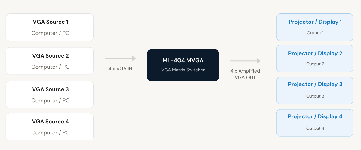
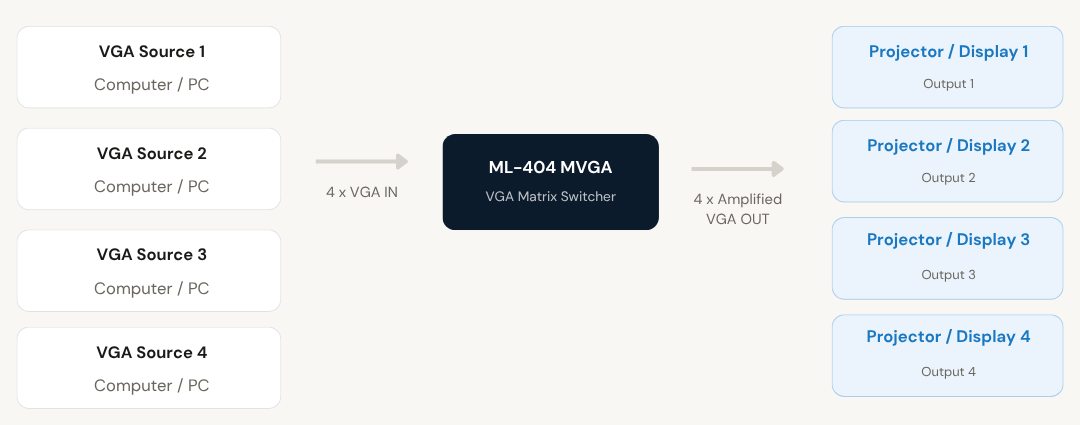
Where the ML-404 MVGA VGA Matrix Switcher performs
Corporate Boardrooms and Conference Rooms
Route any connected laptop or desktop to any projector or display in the room. Multiple presenters can share displays independently or simultaneously without physically reconnecting VGA cables.
Command and Control Rooms
Distribute VGA signals from multiple workstations to a bank of monitors or display walls. The RS232C interface allows control systems and automation platforms to manage channel routing without manual operator intervention.
Training Rooms and Classrooms
Allow an instructor to switch between multiple source computers and project to all displays in the room simultaneously. The front panel keypad provides a simple two-key switching method accessible to non-technical users.
Presentation and Seminar Venues
Enable event organisers to connect up to four source devices and project to multiple screens in the venue. The output blanking function allows individual screens to be cleared between sessions without disconnecting equipment.
Exhibition and Trade Show Installations
Distribute VGA content from a central source to multiple display points across an exhibition stand or show floor. Power-on memory retention ensures the correct routing is restored after daily power cycles without manual reconfiguration.
Broadcast and Media Production Monitoring
Route VGA signals from production computers to monitoring displays at various points in a broadcast facility. The RS232C interface supports integration with broadcast control systems for automated switching.
Full specification sheet
- Model: ML-404 MVGA (RM)
- RS232C Interface
- Remote Contact Closure / Keypad Connector
- RS232C Command Format
- Control and Display
Local Keypad
FAQs about the VGA Matrix Switcher ML-404 MVGA
What is the ML-404 MVGA VGA Matrix Switcher used for?
How do I select a channel using the front panel keypad?
What does the LCD display show during operation?
The unit has a 16×2 character LCD display on the front panel. The top line shows the currently selected input channel and the bottom line shows the corresponding output channel. The position of the output channel indication on the bottom line remains fixed, while the input channel on the top line updates each time a new selection is made.
How do I control the switcher using RS232C?
Connect a control system to the D9 female RS232C connector on the rear panel. The communication parameters are 9600 baud, no parity, 8-bit data, 1 stop bit. Commands are sent in ASCII format using the pattern: input number, asterisk, output number, exclamation mark. For example, the command 2*1! routes input 2 to output 1. To blank an output, send 0 as the input, for example 0*1! blanks output 1. VGA and audio switching can be controlled separately or simultaneously through this interface.
How does the remote contact closure work and what connector is used?
The rear panel has a D9 male connector for connecting Milestone’s optional remote keypad or any external contact closure device. To operate a key remotely, short the corresponding pin to pin 9 (GRD) using a contact switch. For example, shorting pin 1 to pin 9 activates key 1. The remote can be used at a distance of up to 30 metres from the switcher and follows the same two-key press procedure as the local front panel keypad.
How do I blank an output on the ML-404 MVGA?
To blank an output using the front panel keypad, press and hold the relevant output key for 2 seconds. This mutes that output port without affecting other outputs. To blank an output via RS232C, send the command 0*[output number]!, for example 0*2! blanks output 2. Blanking can be applied to any or all output ports independently.
What happens to the channel selection when the unit is powered off and back on?
The ML-404 MVGA retains the previous channel selection in memory. When the unit is powered on again, it automatically restores the last active routing configuration without any manual intervention. This makes the unit suitable for permanent, unattended AV installations where consistent routing must be maintained after power interruptions or scheduled power cycles.
Are other models available with more inputs or outputs?
Yes. Milestone Electronics manufactures the VGA Matrix Switcher in three configurations. The ML-404 MVGA provides 4 inputs and 4 outputs in a 1U enclosure. The ML-804 MVGA provides 8 inputs and 4 outputs, also in a 1U enclosure. The ML-808 MVGA provides 8 inputs and 8 outputs in a 2U enclosure. All three models share the same control interfaces including front panel keypad, RS232C, and remote contact closure.
Can multiple outputs show the same input source simultaneously?
Yes. The ML-404 MVGA supports both independent and simultaneous display configurations. Any input can be routed to one specific output, or the same input can be routed to all four outputs at the same time. Each output carries an independently amplified VGA signal, so routing one input to multiple outputs does not degrade the signal on any of the connected projectors or displays.
Products you may also need
Milestone's VGA Matrix Switcher allows one or more computers to share up to four...
Ready to order or have a specific requirement?
Our team responds within 24 hours. Bulk pricing, custom solutions, and pan-India delivery are available. Talk to an engineer directly about your setup.