
Milestone Electronics
4 Input 1 Output Manual Video Switcher with Scan and IR Remote
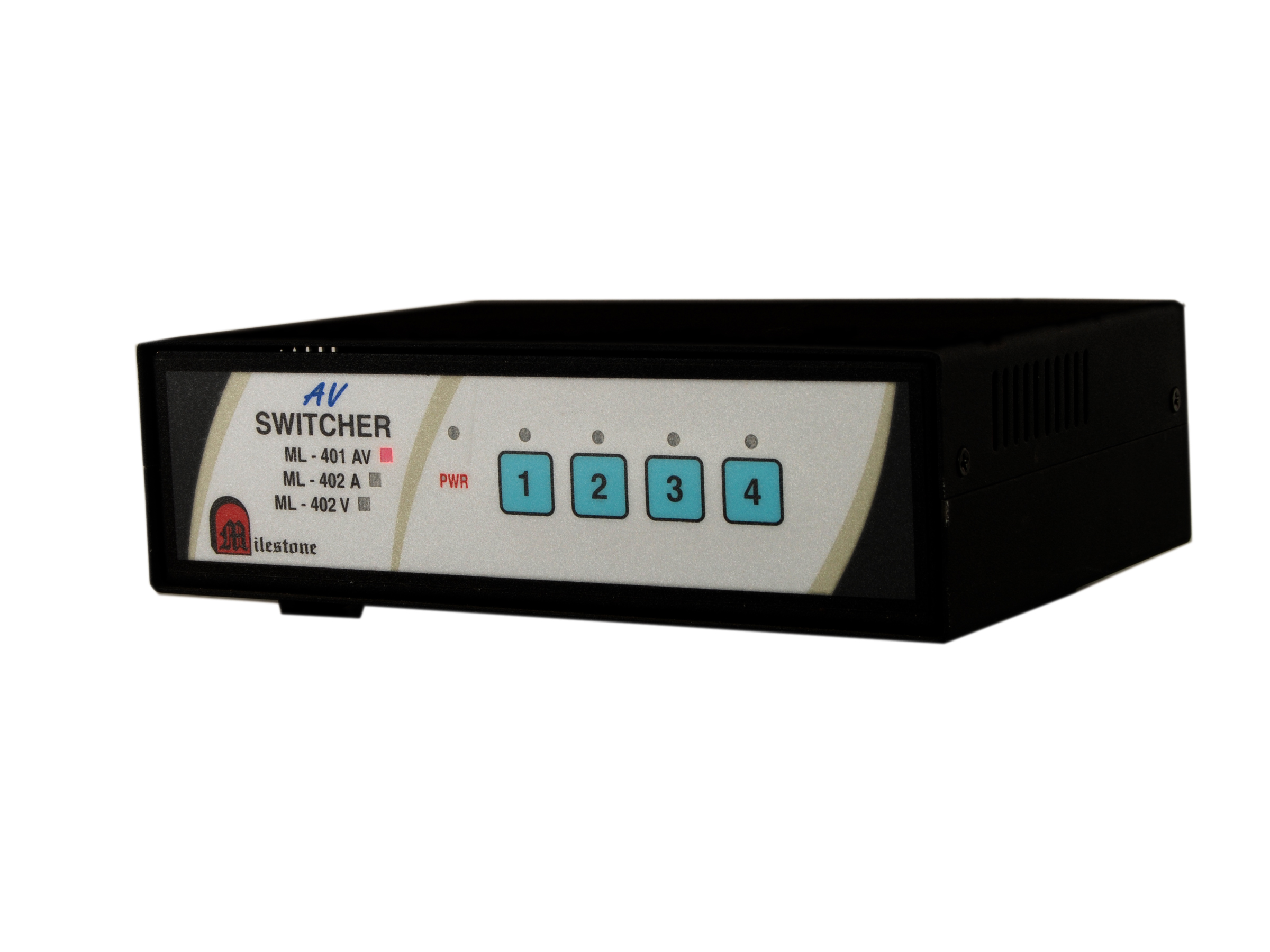
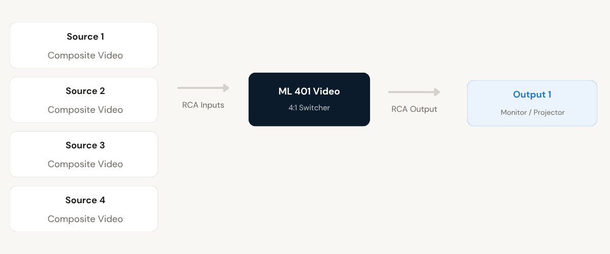
The ML 401 Video is a composite video switcher that allows up to four video sources to be shared with a single projector or display. It supports multiple selection methods including front panel keypad, built-in IR remote, RS232C interface, and automatic scan mode, making it suitable for professional AV switching environments.
- 1 composite AV input distributed to 4 independent AV outputs
- Audio and video signals transmitted together without delay or mismatch
- Each output individually managed and amplified for consistent signal strength
- Video bandwidth up to 90 MHz (-3dB) with 75-ohm impedance matching
- Rugged metal enclosure with captive screw audio connectors for fixed installations
Max Resolution
1080p Full HD
Audio Input
Stereo Analogue
Output
Single HDMI
- In-house manufactured
- 2,000+ clients served
Product Overview
What the ML 401 Video delivers
The ML 401 Video switcher is designed to allow a single display or projector to receive composite video signals from up to four independent sources. It is a plug-and-play device that requires no complex configuration to put into service, and is compatible with standard composite video outputs using RCA connectors.
Channel selection is available through four independent methods: the front panel keypad for local manual operation, the built-in IR remote for wireless control within 2 to 3 metres, RS232C serial interface for system-level integration, and an automatic scan mode that cycles through active input channels at a configurable interval.
The IR remote range can be extended to approximately 30 metres by connecting an external sensor cable to the rear-panel IR EXT. connector. This makes the unit suitable for installations where the switcher is located away from the operator’s position, such as in equipment racks or ceiling-mounted enclosures.
In scan mode, the switcher cycles through input channels at a user-defined dwell time ranging from 10 to 150 seconds. Both the channels to be scanned and the scan time are configurable via the onboard DIP switches, giving system integrators precise control over how the unit behaves in automated display environments.
Video Inputs
Need a quote?
Our team responds within 24 hours with a tailored quote for your project or bulk order.
Key Features
Four-channel composite video switching with flexible control
Manual, IR, RS232, and scan-based selection methods in a single plug-and-play unit compatible with standard composite video infrastructure.
Front Panel Keypad Selection
Any of the four input channels can be selected directly from the front panel keypad. LED indicators on the panel confirm the active channel at a glance. The unit defaults to manual mode when the rear-panel slide switch is set to the manual position.
- Dedicated channel keys for inputs 1 through 4
- LED indication for the currently active channel
- Immediate response with no configuration required
Built-in IR Remote Control
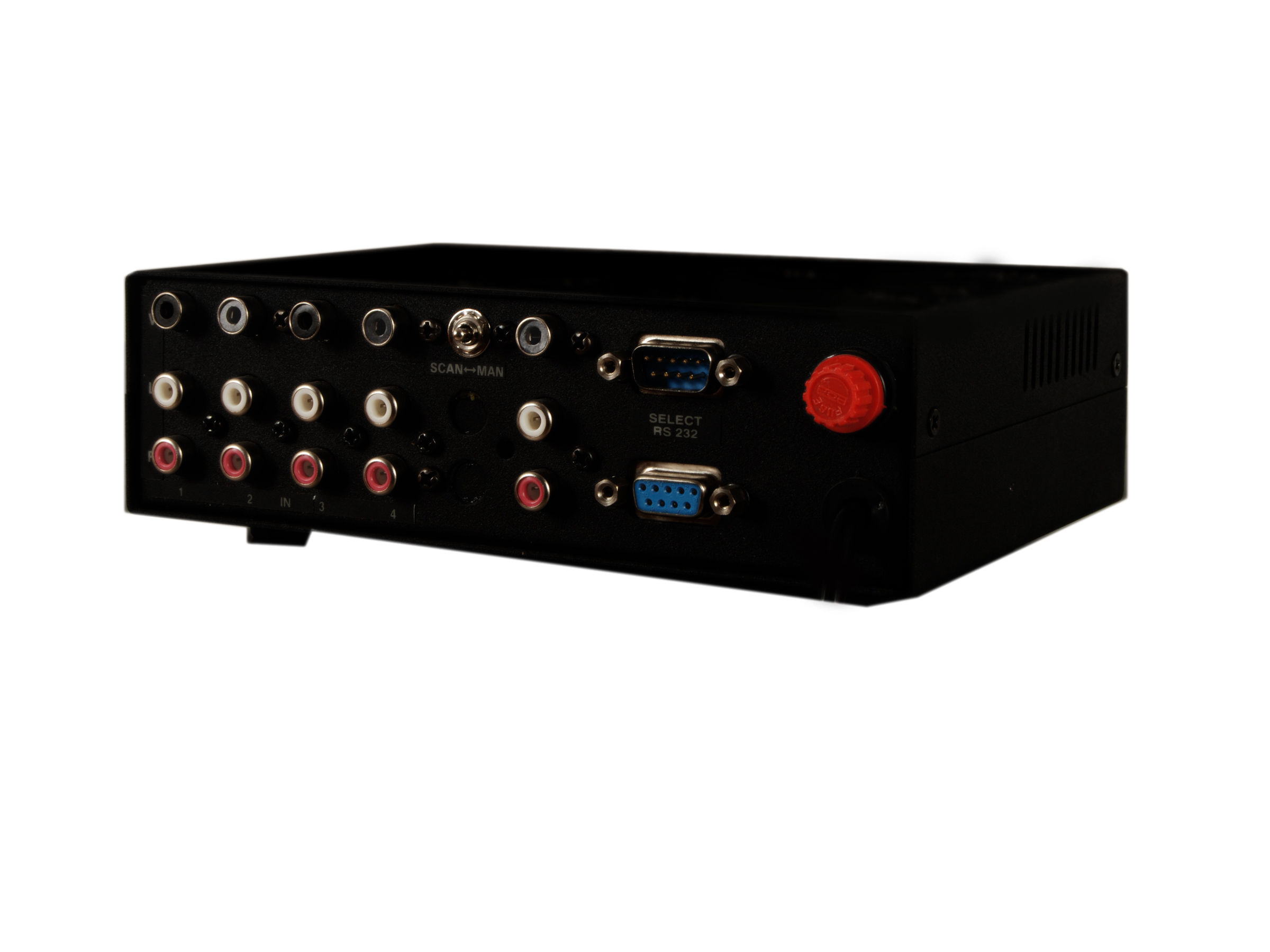
The unit includes an integrated IR remote for wireless channel selection. The remote operates within 2 to 3 metres when pointed at the front panel. For installations where greater reach is needed, the rear-panel IR EXT. connector accepts an external sensor cable that extends IR control range to approximately 30 metres.
- Built-in IR receiver at front panel, 2 to 3 metre operating range
- IR EXT. connector on rear panel for sensor cable attachment
- Extended IR range of approximately 30 metres via external sensor
RS232C Serial Interface
The switcher includes a D9 female RS232C port for remote channel switching from a control system or PC. Channels are selected using simple ASCII commands at 9600 baud, 8-bit, 1 stop bit with no parity. The switcher also sends feedback confirmation on pin 2 whenever a channel is successfully selected.
- D9 female connector on rear panel, pins 3 (Rx) and 5 (GRD)
- ASCII commands: channel 1 = 1!, channel 2 = 2!, and so on up to channel 4
- Feedback confirmation sent on pin 2 after each successful selection
Configurable Scan Mode
Scan mode automatically cycles through selected input channels at a set dwell time. Both the channels to include in the scan cycle and the dwell time per channel are set using the onboard DIP switches. Scan time can be configured from 10 seconds up to 150 seconds in steps, and scanning can be paused and resumed using the remote keypad.
- DIP switch selectable channels for scan inclusion
- Scan dwell time adjustable from 10 to 150 seconds
- Scan LED on front panel indicates scan mode status
Composite Video Compatibility
The ML 401 Video is fully compatible with composite video signals using standard RCA connectors. It connects directly to any composite video source device without the need for adapters or signal conversion, making integration into existing AV installations straightforward.
- 4 RCA input connectors for composite video sources
- 1 RCA output for connection to projector or display
- Standard video cables with RCA male connectors used throughout
Plug and Play Installation
The unit is designed for easy installation without specialist tools or software. It powers from a standard 230V AC supply and operates immediately on connection. The table-top form factor allows standalone deployment in equipment rooms, AV control desks, or presentation environments.
- No driver installation or software configuration required
- 230V AC mains input, table-top enclosure at 288 x 130 x 52 mm
- LED power indicator confirms operational status
Installation
Local keypad, remote contact closure, or RS232C
The ML-2RLC supports three primary installation and control configurations. Select the operating mode using the rear-panel Manual/RS232 select switch before connecting the relevant interface.
01
Manual Mode Setup
Set the rear-panel slide switch to the manual position. Connect up to four composite video sources to the RCA input connectors and the projector or display to the RCA output. Channel selection is then available via the front panel keypad or the built-in IR remote. For extended IR range, connect an external sensor cable to the rear-panel IR EXT. connector to reach approximately 30 metres.
02
Scan Mode Configuration
Power off the unit and configure the DIP switches to set the desired scan dwell time according to the timing table. Press and hold front panel key 1 while powering on the unit. The Scan LED will blink to confirm the timer is correctly set. Power off again, re-set the DIP switches to select which input channels to include in the scan cycle, then power on with the slide switch in the scan position.
03
RS232C Control Wiring
Connect a control system or PC to the D9 female RS232C port on the rear panel. Use pin 3 for Rx and pin 5 for GRD. Set the communication parameters to 9600 baud, 8-bit data, 1 stop bit, and no parity. Send ASCII commands in the format channel number followed by an exclamation mark to select channels. The switcher returns the same string on pin 2 as a confirmation of the selected channel.
04
IR Extender Connection
When the switcher is installed in a location where the built-in front-panel IR receiver cannot be reached by the remote, connect an external IR sensor cable to the EP connector on the rear panel. Position the sensor at a location visible to the remote control. This extends the effective IR control distance to approximately 30 metres from the sensor position.
Where the ML 401 Video performs
Suited to professional environments where multiple composite video sources must be routed to a single display with reliable manual or automated control.
Corporate Presentation Rooms
Route video output from multiple presentation sources, such as DVD players, document cameras, or legacy video equipment, to a single projector. Front panel or IR remote selection allows presenters to switch sources without interrupting the session.
Educational Classrooms
Connect video sources such as VCRs, multimedia players, or camera feeds to a single classroom display. Teachers can select the active source from a remote, and the scan mode can be used to cycle through sources automatically during supervised sessions.
Control Room Monitoring
Use the RS232C interface to integrate the switcher into a centralised control system. Channel selection commands can be issued programmatically from a control panel or automation platform, with confirmation feedback from the switcher on each successful selection.
CCTV and Security Monitoring
Cycle through multiple composite video camera feeds on a single monitor using scan mode. The configurable dwell time allows each camera channel to be displayed for a set duration before the switcher moves to the next, removing the need for dedicated monitors per camera.
Broadcast and Production Environments
Switch between composite video feeds from multiple sources during live production or review sessions. The RS232C interface enables integration with production control systems, allowing programmatic source switching as part of an automated workflow.
AV Equipment Rack Installations
Install the switcher within an equipment rack and use the IR extender connector to position the IR sensor at the operator's location. This allows remote-based channel selection without requiring physical proximity to the rack, keeping the installation clean and accessible.
Full specification sheet
- Relay Output
- Video Connectors
- Control Interfaces
- IR Remote
- Scan Mode
- Indicators
- Power and Physical
FAQs about the ML 401 Video Switcher
What type of video signals does the ML 401 Video support?
The ML 401 Video is designed for composite video signals. It uses standard RCA connectors on both inputs and output, and is fully compatible with any device that produces a composite video output. Standard video cables with RCA male connectors are used throughout the installation.
How do I select a channel on the ML 401 Video?
The ML 401 Video offers four methods of channel selection. You can use the front panel keypad to press the desired channel key directly. The built-in IR remote can be used for wireless selection within 2 to 3 metres of the unit. Alternatively, the RS232C interface allows a connected control system or PC to send ASCII commands to select channels. Scan mode is also available, which cycles through configured channels automatically.
Can I extend the IR remote range beyond 2 to 3 metres?
Yes. The rear panel of the ML 401 Video includes an IR EXT. connector (EP type). By connecting an external IR sensor cable to this connector and positioning the sensor at the desired control location, the effective IR remote range is extended to approximately 30 metres. This is useful when the switcher is installed in an equipment rack or a location that is not directly accessible to the operator.
How do I configure the scan mode dwell time?
To set the scan dwell time, first power off the unit and configure the DIP switches according to the timing table provided in the manual. Then press and hold front panel key 1 while powering the unit on. If the timer is correctly set, the Scan LED will begin blinking as confirmation. Power off again, reconfigure the DIP switches to select which channels should be included in the scan cycle, and power back on with the slide switch in the scan position. The default scan time is 20 seconds per channel, and times range from 10 to 150 seconds.
What are the RS232C command formats for channel selection?
Channel selection via RS232C uses simple ASCII commands. To select Channel 1, send the string 1! (decimal bytes 31, 21). Channel 2 uses 2!, Channel 3 uses 3!, and Channel 4 uses 4!. Communication parameters are 9600 baud, 8-bit data, 1 stop bit, and no parity. After each successful channel selection, the switcher sends the corresponding command string back on pin 2 of the D9 female connector as a confirmation.
Can I select which channels are included in the scan cycle?
Yes. The DIP switches on the unit allow individual channels to be included or excluded from the scan cycle. For example, to scan only channels 1, 3, and 4, set DIP switches 1, 3, and 4 to ON and leave the others OFF. This is set after completing the scan time configuration step and before powering the unit on in scan mode. Channels with no active source connected can be excluded from the scan to avoid displaying a blank or unstable input.
Does the ML 401 Video require any special installation or drivers?
No. The ML 401 Video is a plug-and-play device that requires no driver installation or software configuration. Connect the composite video source devices to the RCA input ports, connect the output to the display or projector, and supply 230V AC power. The unit is immediately operational in manual mode. RS232C integration requires only a serial connection using the specified pin configuration and communication parameters.
What is the difference between the ML 401 Video and the ML 801 Video?
The ML 401 Video accepts 4 composite video input sources and routes one to a single output. The ML 801 Video accepts 8 composite video input sources with the same single output configuration. Both models share the same control methods, form factor dimensions, and mains input specification. The choice between them depends on how many source devices need to be connected to the switcher.
Products you may also need
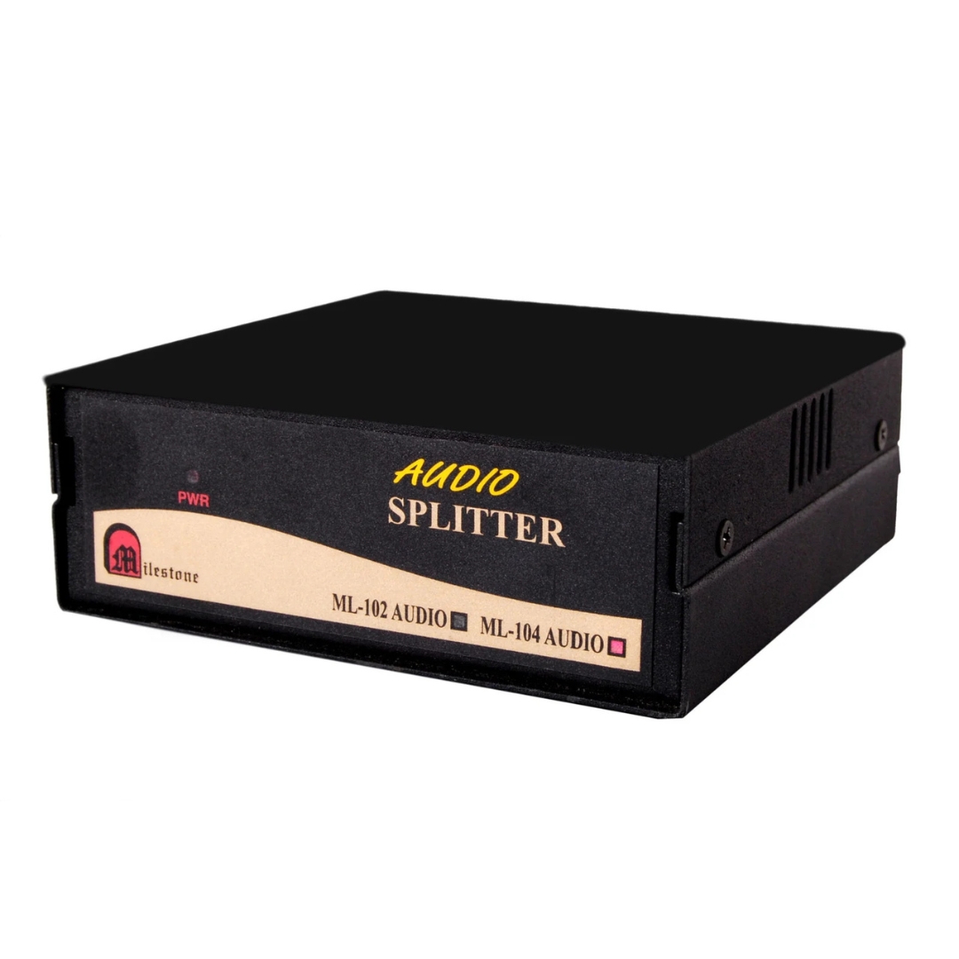
The ML 104 Audio Splitter distributes a single RCA audio source to four outputs...
Ready to order or have a specific requirement?
Our team responds within 24 hours. Bulk pricing, custom solutions, and pan-India delivery are available. Talk to an engineer directly about your setup.